


")


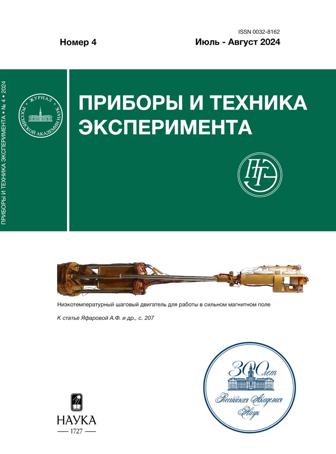
Низкотемпературный шаговый двигатель для работы в сильном магнитном поле
- Autores: Яфарова А.Ф.1,2, Холин Д.И.1, Сосин С.С.1
-
Afiliações:
- Институт физических проблем им. П.Л. Капицы Российской академии наук
- Национальный исследовательский университет “Высшая школа экономики”
- Edição: Nº 4 (2024)
- Páginas: 207-214
- Seção: ЛАБОРАТОРНАЯ ТЕХНИКА
- URL: https://cijournal.ru/0032-8162/article/view/681088
- DOI: https://doi.org/10.31857/S0032816224040254
- EDN: https://elibrary.ru/NXLLET
- ID: 681088
Citar
Texto integral

Resumo
Разработана конструкция шагового электродвигателя, предназначенного для вращения образца в экспериментальной ячейке, находящейся внутри криостата с откачкой 3Не. Устройство на основе ротора со скрещенными электрическими обмотками работает в постоянном магнитном поле, создаваемом сверхпроводящим соленоидом. Опытный образец двигателя был установлен на СВЧ-спектрометр проходного типа с прямоугольным резонатором. Для его испытания измерены угловые зависимости спектра магнитного резонанса в хорошо изученном антиферромагнетике MnCO3 при температурах 0.5–7.5 К в диапазоне углов ±100° от начального положения. Исследован перегрев ячейки и криостата и проведена оценка тепловыделения в процессе работы механизма.
Texto integral
Sobre autores
А. Яфарова
Институт физических проблем им. П.Л. Капицы Российской академии наук; Национальный исследовательский университет “Высшая школа экономики”
Autor responsável pela correspondência
Email: afyafarova@edu.hse.ru
Rússia, Москва; Москва
Д. Холин
Институт физических проблем им. П.Л. Капицы Российской академии наук
Email: afyafarova@edu.hse.ru
Rússia, Москва
С. Сосин
Институт физических проблем им. П.Л. Капицы Российской академии наук
Email: afyafarova@edu.hse.ru
Rússia, Москва
Bibliografia
- Turov E.A. Physical properties of magnetically ordered crystals. New York: Academic Press, 1965. https://doi.org/10.1063/1.1149138
- Bhattacharya A., Tuominen M.T., Goldman A.M. // Rev. Sci. Instrum. 1998. V. 69. P. 3563. https://doi.org/10.1063/1.1149138
- Palm E.C., Murphy T.P. // Rev. Sci. Instrum. 1999. V. 70. P. 237. https://doi.org/10.1063/1.1149571
- Andreeva O.A., Keshishev K.O. // JETP Lett. 1987. V. 46. P. 200.
- Ohmichi E., Nagai S., Maeno Y., Ishiguro T., Mizuno H., Nagamura T. // Rev. Sci. Instrum. 2001. V. 72. P. 1914. https://doi.org/10.1063/1.1347982
- Yeoh L.A., SrinivasanA., Martin T.P. et al. // Rev. Sci. Instrum. 2010. V. 81, P. 113905. https://doi.org/10.1063/1.3502645
- Малков М.П., Данилов И.Б., Зельдович А.Г., Фрадков А.Б. Справочник по физико-техническим основам глубокого охлаждения. Москва: Госэнергоиздат, 1963.
- Borovik-Romanov A.S. // Sov. Phys. JETP. 1959. V. 9. P. 539.
- Borovik-Romanov A.S., Kreines N.M., Prozorova L.A. // Sov. Phys. JETP. 1964. V. 18. P. 46.
Arquivos suplementares


